Step #1 - How-to set a Style to Raster Coverages |
|---|
Step #1.0.1 - Preparing to load the Coverages in MapPanel
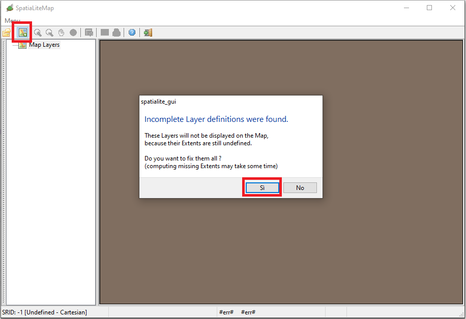
Press the icon shown in the toolbar:
- a warning message will be displayed on the screen
- this happens just because there are one or more Coverages still lacking the definition of their overall Extent, that is absolutely required.
- Click the Yes button and continue
|
 |
Step #1.0.2 - Loading the Coverages in MapPanel
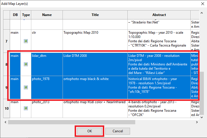
On the dialog box:
- Select one (or even more) Coverage(s) to be loaded in MapPanel.
- Press the OK button so to confirm.
Useful notes
You can load all Coverages in a single shot or alternatively you can load only one at each time; it's not relevent, do as you wish best.
|
 |
Step #1.1 - Enabling Raster AutoSwitch |
|---|
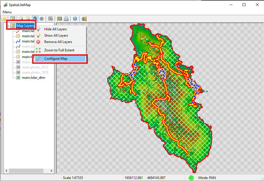
Step #1.1.1 - Opening the Configure Map dialog box
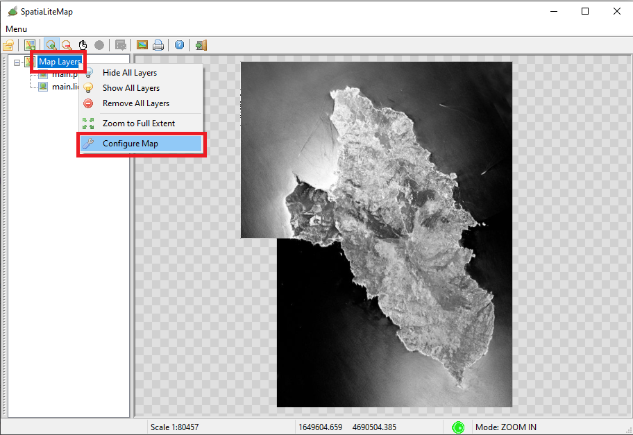
From the root Map Layer node in the Tree View:
- press the mouse right button
- a context menu will be displayed on the screen
- Click the Configure Map menu item
|
 |
Step #1.1.2 - Configuring the Map
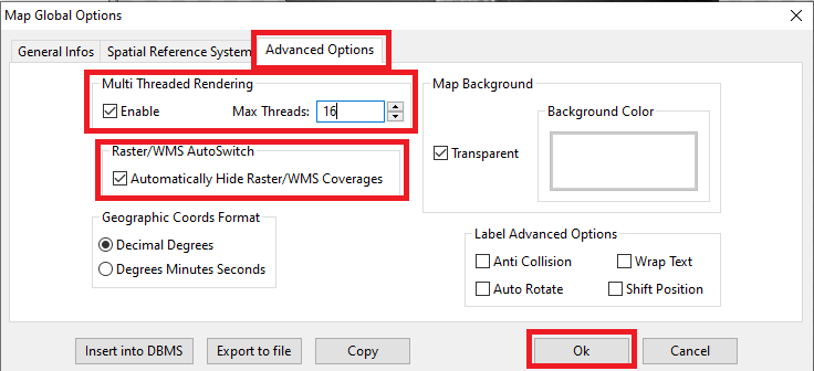
On the dialog box:
- Be sure to enable MultiThreading so to ensure a fast rendering.
- As rule of the thumb, requesting a max number of concurrent threads equal to the double of the physical+logical cores of your CPU seems to ensure an optimal performace level.
- Be sure to enable Raster/WMS AutoSwitch
- Press the OK button so to confirm.
|
 |
Step #1.1.3 - How the Raster/WMS AutoSwitch property works
- Raster/WMS Coverages are usually opaque, so activating two or more Coverages at the same time will simply be a useless wast of time just because the upper Coverage will completely overpaint the lower ones.
- When the Raster/WMS AutoSwitch property is enabled, the Map Panel itself will take care of automatically hide any other Raster/WMS layer except the one beign currently selected.
This is a useful option ensuring better performances in many cases.
|
 |
Step #1.2 - Styling the lidar_dtm Raster Coverage |
|---|
Step #1.2.1 - How to apply a Quick Style
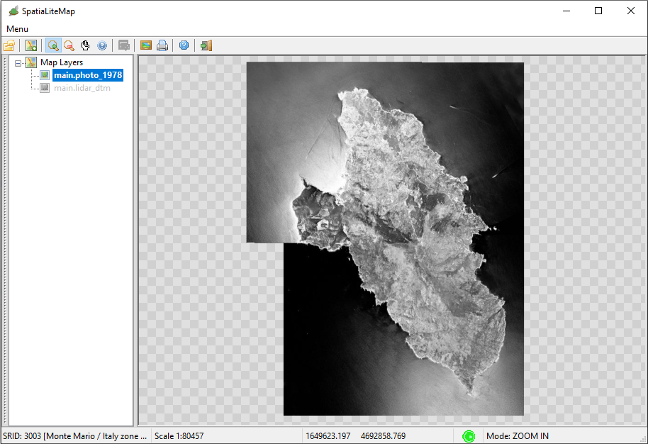
The lidar_dtm Coverage is a DataGrid based on FLOAT pixel values.
Consequently the default style will simply be a rather dull and not significat GrayScale (see the side figure).
We can surely get a much more pleasent visual rendering by applying an appropriate Quick Style
A Quick Style is just a simple dynamic Style that you can easily define in the most user friendly way by using the appropriate Wizards. Note:
- Quick Styles are transient: they only live in the current session, and when the session finishes they vanish forever.
- However Quick Styles are standard SLD/SE styles, so you can easily transform them into persistent standard styles.
|
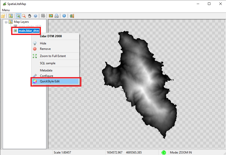
From the main.lidar_dtm node in the Tree View:
- press the mouse right button
- a context menu will be displayed on the screen
- Click the QuickStyle Edit menu item
|
 |
Step #1.2.2 - Styling the lidar_DTM Coverage
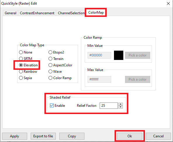
On the dialog box:
- open the ColorMap tab.
- select the built-in Elevation Color Map.
- enable the ShededRelief option.
- set Relief Factor to 25 (an effective by not too much exaggerated factor).
- and finally press the Ok button so to confirm.
|
 |
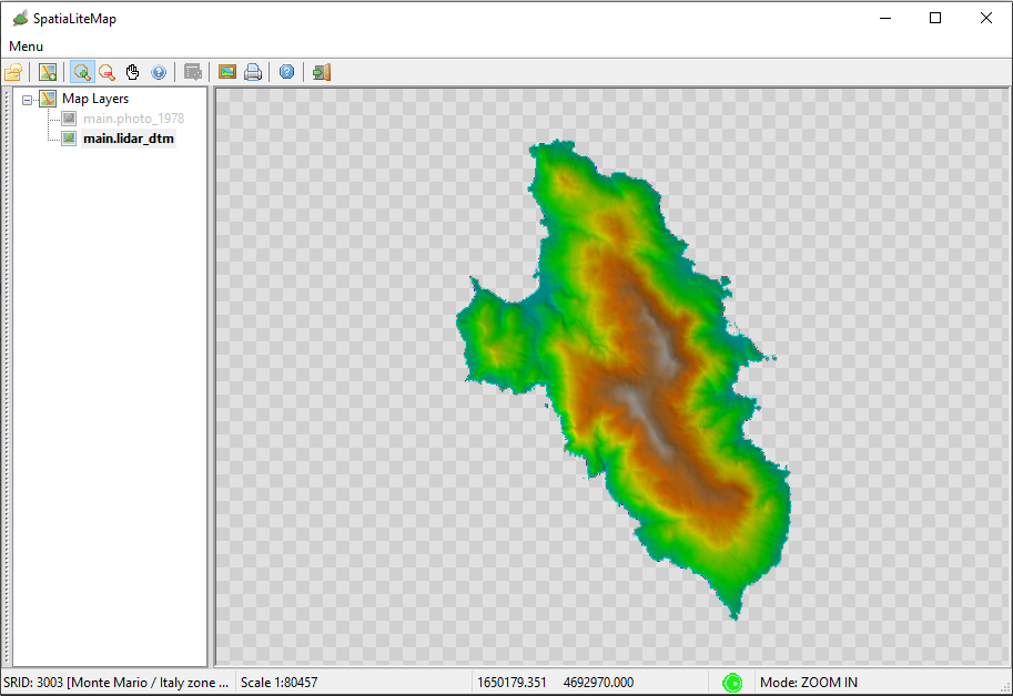
Step #1.2.3 - Verifying the Quick Style
As you can easily notice, now after applying an appropriate Quick Style the lidar_dtm Coverages shows an impressive enhancement (see the side figure).
|
 |
Step #1.3 - Styling the photo_2013 Raster Coverage |
|---|
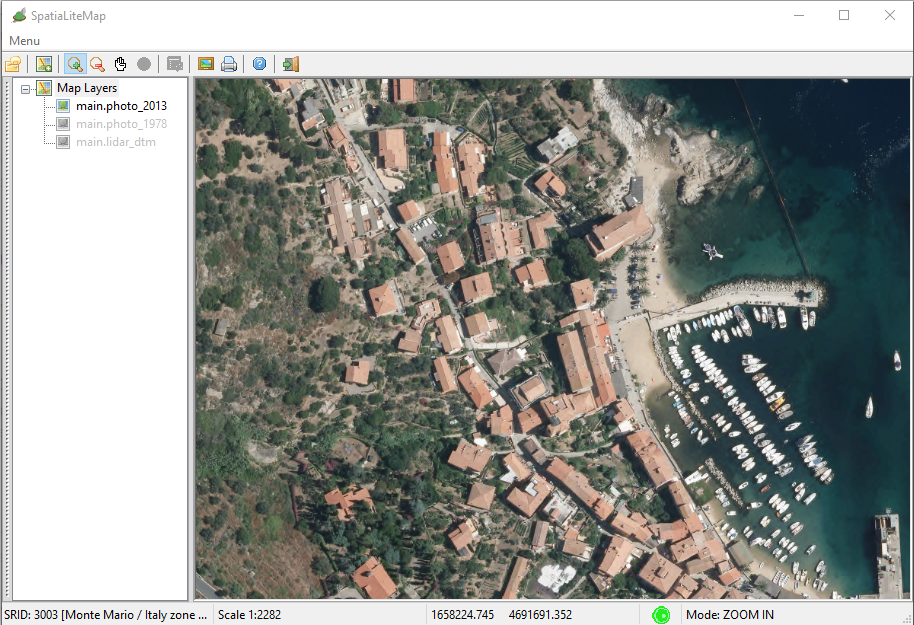
Step #1.3.1 - Default style for the photo_2013 Coverage
If you remember, when creating the photo_2013 Coverage we already defined a basic mapping between the 4 Bands supported by this datasource and their correspondent Colors/Wavelengths.
- Band #0 = Red
- Band #1 = Green
- Band #2 = Blue
- Band #3 = NIR (Near InfraRed)
As a direct consequence now the default style corresponds to a Natural Color RGB image.
But we can squeeze much more useful informations from such an advanced datasource, we just have to define few appropriate Quick Styles
|
|
|
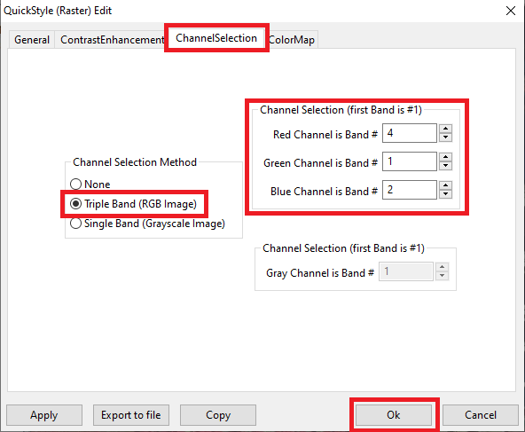
Step #1.3.2 - Creating a False Color Quick Style (NirRG)
On the dialog box:
- open the ChannelSelection tab.
- enable the Tripe Band (RGB Image) method.
- select Band #4 (Nir) as the Red channel.
- Note: in the specific context of SLD/SE styles the first band has index=1
- select Band #1 (Red) as the Green channel.
- select Band #2 (Green) as the Blue channel.
- and finally press the Ok button so to confirm.
|
|
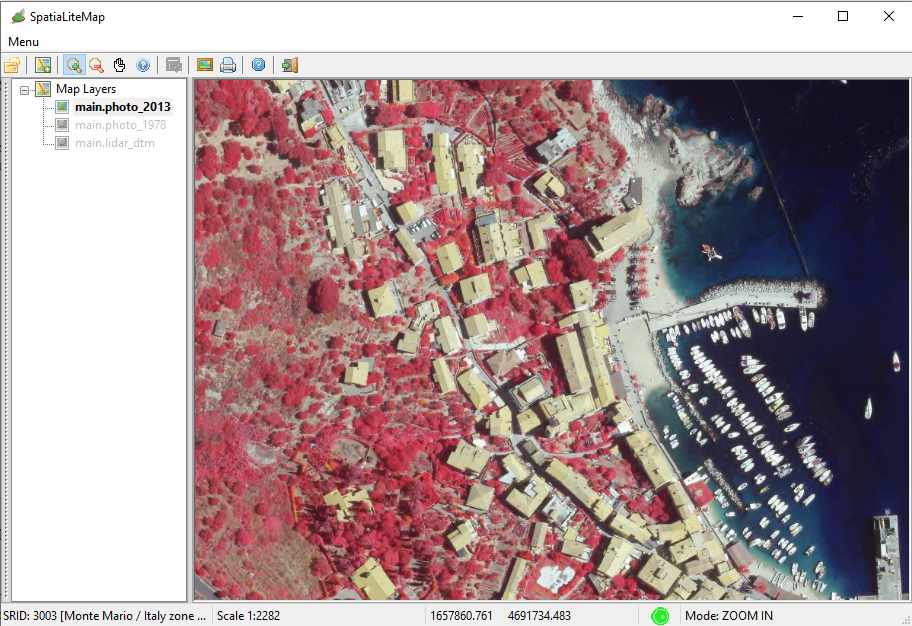
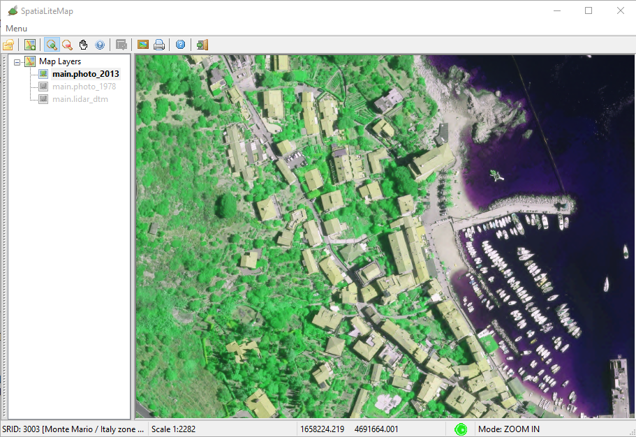
Step #1.3.3 - Visual check - the NirRG Quick Style
|
The NIR + Red + Green (NirRG) band combination leads to False Color images specificaly intented for putting in evidence the Vegetation
|
|
|
Step #1.3.4 - Another False Color Quick Style - NirGB
|
The NIR + Green + Blue (NirGB) band combination is specificaly intented for putting in evidence the Conifers
|
|
|
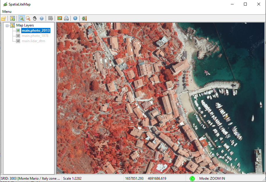
Step #1.3.5 - Yet another False Color Quick Style - RNirG
|
The Red + NIR + Green (RNirG) band combination is best suited for discriminating between Urban and Agicultural areas.
|
|
|
Step #1.3.6 - NDVI (Normalized Difference Vegetation Index)
We haven't yet finished to fully style the amazing 4-Bands photo_2013 Coverage.
We still have to configure the QuickStyles based on Numerical Indices, such as the NDVI computed as follows:
         (Nir - Red)
NDVI = ---------------
         (Nir + Red)
|
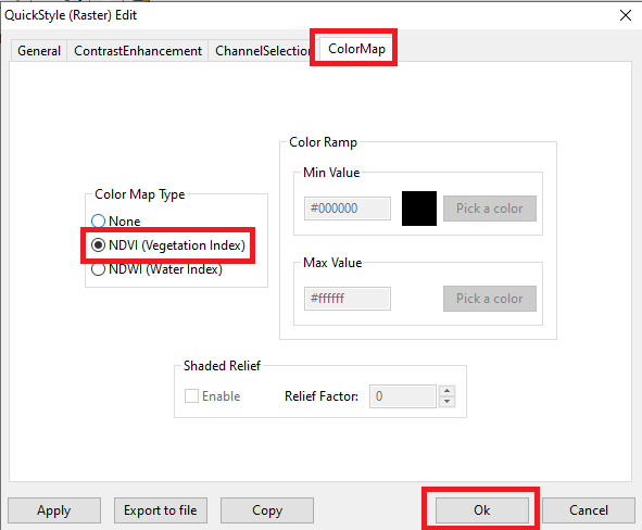
On the dialog box:
- open the ColorMap tab.
- select the NDVI (Vegetation Index) Color Map.
- press the Ok button so to confirm.
|
|
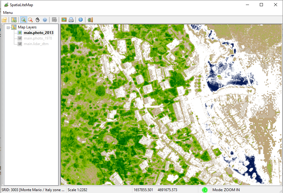
Step #1.3.7 - Visual check - the NDVI Quick Style
NDVI is specifically intended for discriminating the vegetation (the denser the vegetation cover, the more intense the green color will be).
In ultimate analysis NDVI values are directly proportional to the concentration of clorophyll
|
|
|
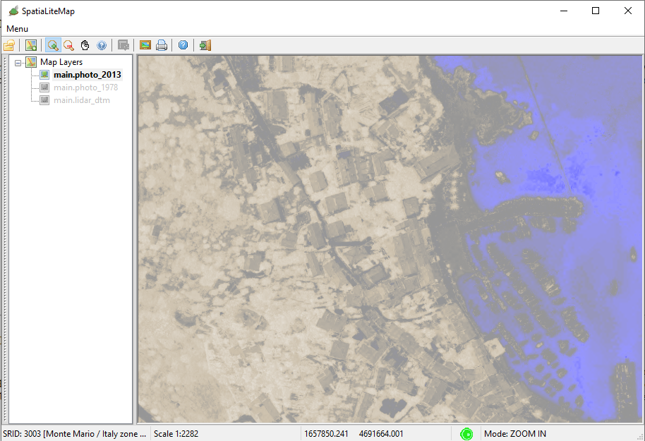
Step #1.3.8 - NDWI (Normalized Difference Water Index)
The NDWI (accordingly to McFeeters 1996) is defined as follows:
         (Green - Nir)
NDVI = -----------------
         (Green + Nir)
NDWI is specifically intended for discriminating liquid water, but in the McFeeters acception can be easily fooled by dark shadows.
|
|
|
Step #1.4 - How-to transform a Quick Style into a Registered Style |
|---|
Step #1.4.1 - Exporting a Quick Style
Just to summarize the whole question:
- Quick Styles are easy, but the are transient.
- Registered Styles are a little bit more complex, but they are persistent.
Users will quicly realize that in the case of a datasource supporting so many different styles, such as photo_2013 is, handling a set of persistent registered styles will be easier and faster.
Happily enough, transforming Quick Styles into persistent registered styles isn't at all difficult.
You just have to:
- export the Quick Style into an external file.
- edit this file adjusting few details.
- and you'll finally able to import the edited file as a persistent registered style.
|
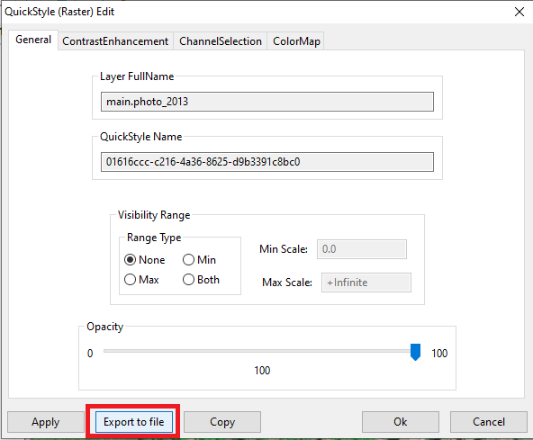
On the QuickStyle dialog box:
- click the Export to file button.
- save somewhere the exported file.
|
|
Step #1.4.2 - Editing the exported SLD/SE Style
SLD/SE Styles simply are XML files, so you can easily edit them using any text editor of your choice.
- you are now simply required to set sensible values to Name, Title and Abstract
- Note: assigning meaningful values to these fields could easily appear just an annoying waste of time, but once that you'll have accumulated many different Styles you'll quickly discovert that it's the only way to avoid the chaos and preserve a proper order.
- when done, save and exit.
|
<?xml version="1.0" encoding="UTF-8"?>
<CoverageStyle version="1.1.0"
    xsi:schemaLocation="http://www.opengis.net/se http://schemas.opengis.net/se/1.1.0/FeatureStyle.xsd"
    xmlns="http://www.opengis.net/se" xmlns:ogc="http://www.opengis.net/ogc"
    xmlns:xlink="http://www.w3.org/1999/xlink"
    xmlns:xsi="http://www.w3.org/2001/XMLSchema-instance">
    <Name>RNirG</Name>
    <Description>
        <Title>False Color: RNirG</Title>
        <Abstract>a false color Style intended for 4-Bands ortophoto
	    (Urban-Agriculture)</Abstract>
    </Description>
    <Rule>
        <RasterSymbolizer>
            <Opacity>1.00</Opacity>
            <ChannelSelection>
                <RedChannel>
                    <SourceChannelName>1</SourceChannelName>
                </RedChannel>
                <GreenChannel>
                    <SourceChannelName>4</SourceChannelName>
                </GreenChannel>
                <BlueChannel>
                    <SourceChannelName>2</SourceChannelName>
                </BlueChannel>
            </ChannelSelection>
        </RasterSymbolizer>
    </Rule>
</CoverageStyle>
|
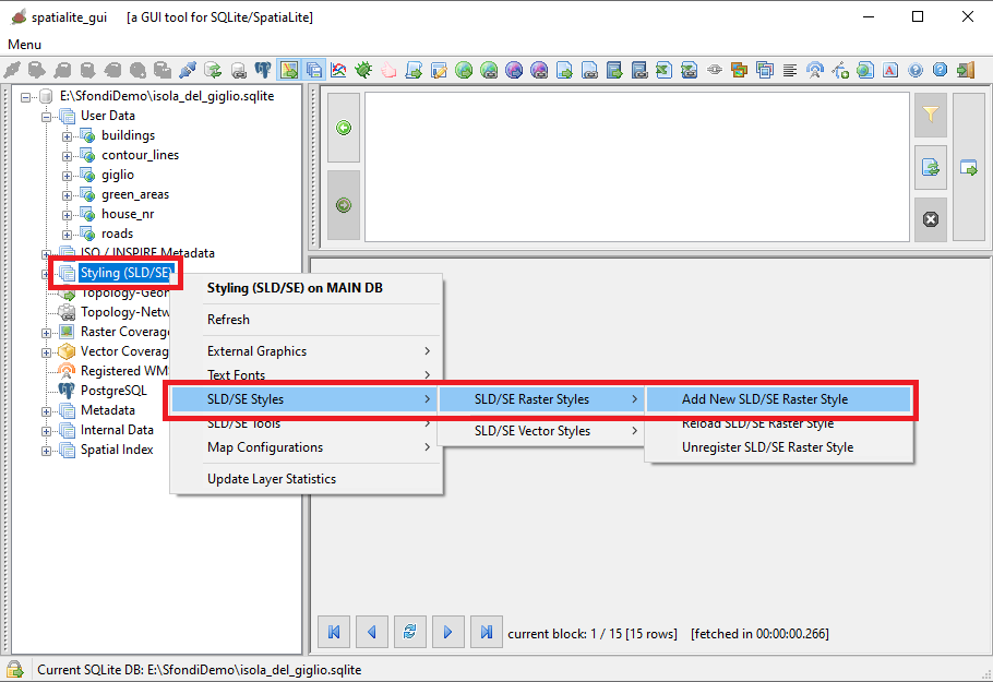
Step #1.4.3 - Importing SLD/SE files as Registered Styles
From the Styling (SLD/SE) node in the Tree View:
- press the mouse right button
- a context menu will be displayed on the screen
- Click the SLD/SE Styles menu item
- a further context menu will be displayed
- Click the SLD/SE Raster Styles menu item
- yet another context menu will be displayed
- Click the Add New SLD/SE Raster Style menu item
|
|
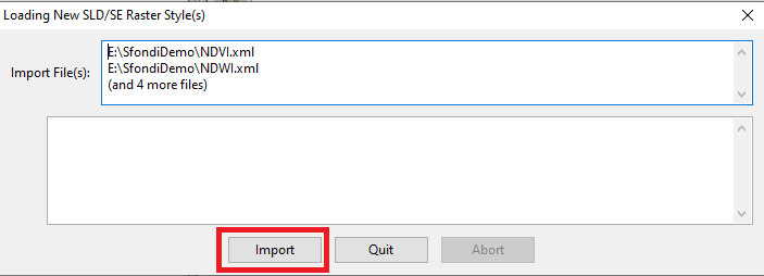
Step #1.4.4 - Confirming the request to import SLD/SE files
On the dialog box:
Just for the sake of curiosity, all registered SLD/SE Raster Styles are stored into the SE_raster_styles table.
Similarly all registered SLD/SE Vector Styles are stored into the SE_vector_styles table.
|
|
|
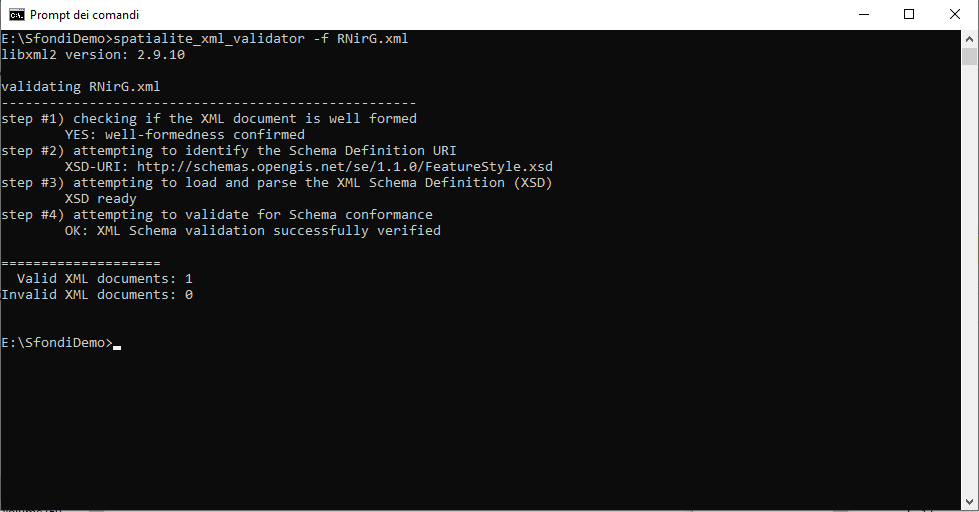
Step #1.4.5 - How-to Debug XML troubles
SLD/SE Styles are XML files, and as any other XML document can be subject to several errors: malformed, missing or misplaced tags, logical violations of the intended schema, forbidden values and so on.
Correcting such errors can easily become an irritating and frustrating task.
|
In such an evenience using the spatialite_xml_validator CLI tool can make your life sweeter and easier.
This basically simple tool will parse any XML document then reporting in a very detailed and useful way any issue eventually found.
|
|
|
Step #1.5 - Associations between Registered Styles and Coverages |
|---|
Step #1.5.1 - Opening the appropriate Dialog Box
Until now we've just registered several persistent Styles.
It's now time to register a persistent link between these Styles and the Coverage(s) they are intended to support.
|
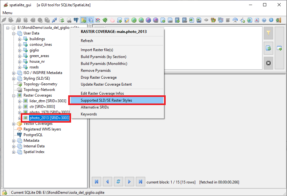
Expand the Raster Coverages node in the Tree View:
- position the mouse on the intended Coverage node
- press the mouse right button
- a context menu will be displayed on the screen
- Click the Supported SLD/SE Raster Styles menu item
|
Note: the association between Registered Styles and Vector Coverages is implemented in a closely similary fashion.
|
|
|
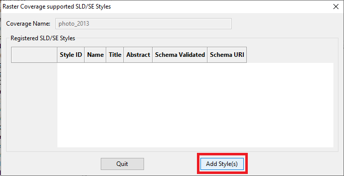
Step #1.5.2 - Beginning the selection of associated Styles
|
As you can see on the side picture, the list of the Styles associated to the current Coverages is initially empty.
|
On the Dialog Box:
- Press the Add Style(s) button.
|
|
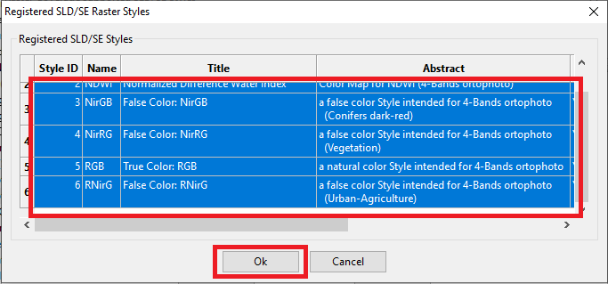
Step #1.5.3 - Selecting Styles from the List
On the Dialog Box:
- Select the Style(s) that you intend to associate to the current Coverage.
- Note: multiple selection is supported.
- when you've completed your selection press the Ok button in order to confirm.
|
|
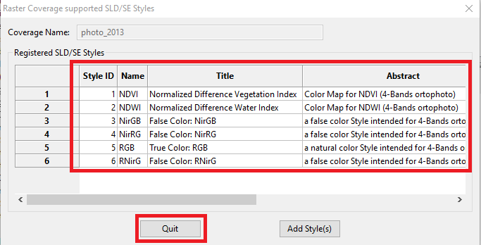
Step #1.5.4 - Final check
As you can check on the side figure, all the intended Registered Styles are nowpersistently associated to the photo_2013 Raster Coverage.
On the Dialog Box:
|
|
Step #1.6 - Styling the CTR Raster Coverage |
|---|
If you remember, when we populated the Monochrome (1-bit) CTR Coverages, we intentionally avoided to create the Upper Leverls of the MultiResolution Pyramid.
This one is a potentially hazardous conditions, so we anticipated that some appropriate remedy was to be applied when styling the Coverage; time has now come.
|
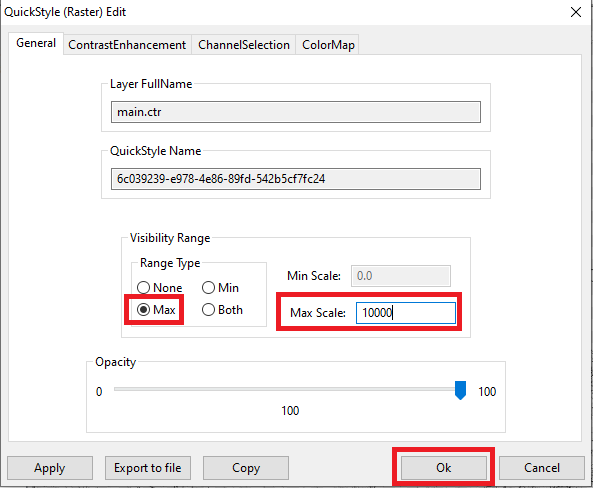
On the QuickSyle dialog box:
- open the General tab.
- enable the Max scale option.
- set Max Scale to 10000; this will safely avoid that the Coverage will be shown at dangerous resolutions.
- and finally press the Ok button so to confirm.
Note: setting Upper and/or Lower Scale limits to the Visibily Range of both Raster and Vector Coveges is often very useful, and easily leads to much more intelligible maps.
All Sample Databases uses this option for many Coverages; documenting all them will be simply boring.
Please check the settings for each Coverage directly on the databases.
|
|
 |
Step #2 - How-to set a Style to Vector Coverages |
|---|
Step #2.1 - Styling a Linestrings Coverage
Styling Vector Coverages is more or less the same as styling Raster Coverages.
Both QuickStyles and Registered Styles are supported also for Vector Coverages, exactly as is the persistent association between Styles and Coverages.
In a general way, understanding Vector Styles is simpler and more intuitive than understanding Raster Styles, so we'll explain just two examples in this tutorial.
|
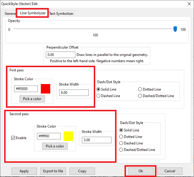
Let's start with an advanced Line Symbolizer supporting the roads Vector Coverage and based on a double pass stroke.
On the QuickStyle Dialog Box:
- open the Line Symbolizer tab.
- set an appropriate color and a rather generous width for the first pass.
- enable the Second pass option.
- set a contrasting color and a lower width for the second pass.
- and finally press the Ok button so to confirm.
|
|
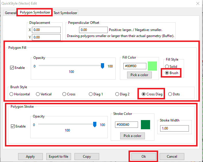
Step #2.2 - Styling a Polygons Coverage
Now we'll set an advanced Polygon Symbolizer supporting the green_areas Vector Coverage and based on a transparent brush having a cross diagonal pattern.
On the QuickStyle Dialog Box:
- open the Polygon Symbolizer tab.
- enable both Fill and Stroke and set an appropriate color for each one.
- be sure to select the Brush option then selecting the Cross Diag pattern.
- and finally press the Ok button so to confirm.
|
|
Step #3 - How-to permanently save a Map Configuration |
|---|
Step #3.1 - About Map Configuration
All right, now the Giglio sample is finally complete and fully styled, as you can see on the side picture.
Note: check the visual effect of the advanced Styles applied to roads and green_areas
We have spent some time in order to reach this result, and it would be a real pity not registering in a persistent way what we have achieved with so much patient effort.
So we now have to save a permanent MapConfiguration, that is an XML document representing all current settings that will be registered for future usage into the rl2_map_configurations table.
Don't be afraid, because it's a fully automatic process supported by a specific wizard.
|
From the root Map Layers node in the Tree View:
- press the mouse right button
- a context menu will be displayed on the screen
- Click the Configure Map menu item
|
|
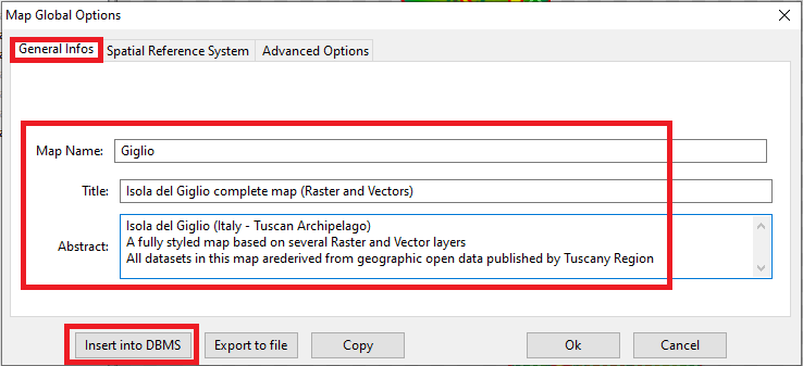
Step #3.2 - Saving the current Map Configuration
On the Map Global Options dialog box:
- open the General Infos tab.
- set sensible values to Map Name, Title and Abstract
- Note: I suppose there is no need to repeat once more the importance of inserting accurate metadata.
It will cost you just few minutes, but it could avoid many future troubles requiring much more time to be fixed.
- and finally press the Insert into DBMS button so to confirm.
|
|
Step #4 - Advanced wizards for creating SLD/SE Styles |
|---|
Step #4.1 - Advanced wizards for Raster Styles
As we've already seen, the most recent version of spatialite_gui implements several wizards supporting Quick Styles in a really easy and user friendly fashion.
And we've already discovered that transforming QuickStyles into Registered Styles is a rather trivial task.
What we've still do learn is that spatialite_gui implements further useful wizards allowing to directly create and store Registered Styles, of both the Raster and Vector types.
|
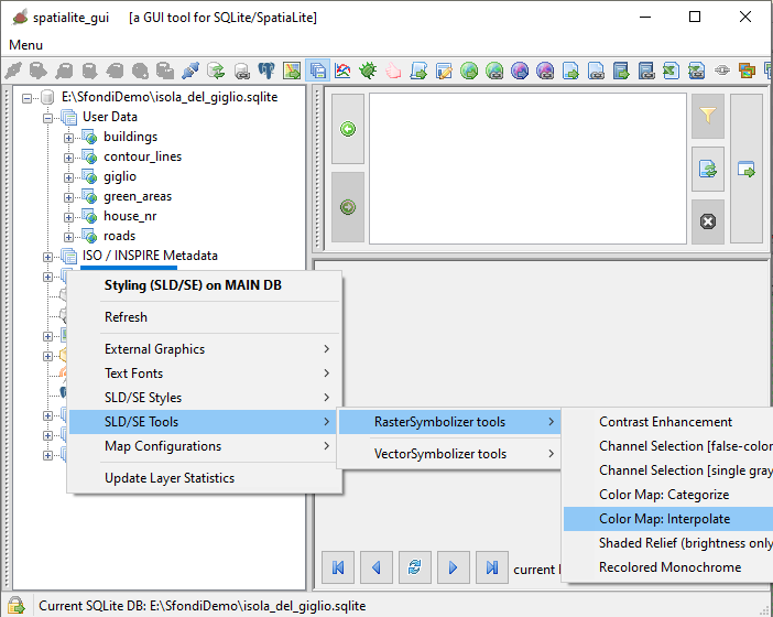
From the Styling (SLD/SE) node in the Tree View:
- press the mouse right button
- a context menu will be displayed on the screen
- Click the SLD/SE Tools menu item
- a further context menu will be displayed
- Click the RasterSymbolizer tools menu item
- yet another context menu will be displayed
- Click one the menu items corresponding to each specific wizard
No practical example will be exposed about the wizards; they are supposed to be quite intuitive and self-explanatory to avoid a boring step by step examination.
What you've already learned about QuickStyles should be enough to guide you.
|
|
|
Step #4.2 - Advanced wizards for Vector Styles
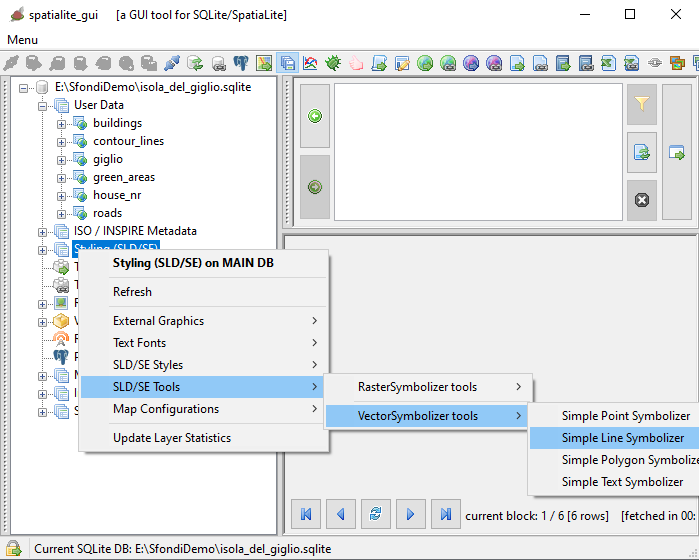
From the Styling (SLD/SE) node in the Tree View:
- press the mouse right button
- a context menu will be displayed on the screen
- Click the SLD/SE Tools menu item
- a further context menu will be displayed
- Click the VectorSymbolizer tools menu item
- yet another context menu will be displayed
- Click one the menu items corresponding to each specific wizard
Final hint
Wizards are surely easy and user friendly, but they are bound to a rigid and simplified logic that inevitably limits them in many ways.
When you absolutely need all the unconstrained firepower that SLD/SE Styles can provide then you need to handwrite your XML code.
This could seem an intimidating difficult task, but you will be surprised in discovering how it could become easy if you start from some simpler wizard-generated style.
This will act as a kind of template that you can easily and quickly extend and expand as you wish better accordingly to your specific requirements.
|
|
|