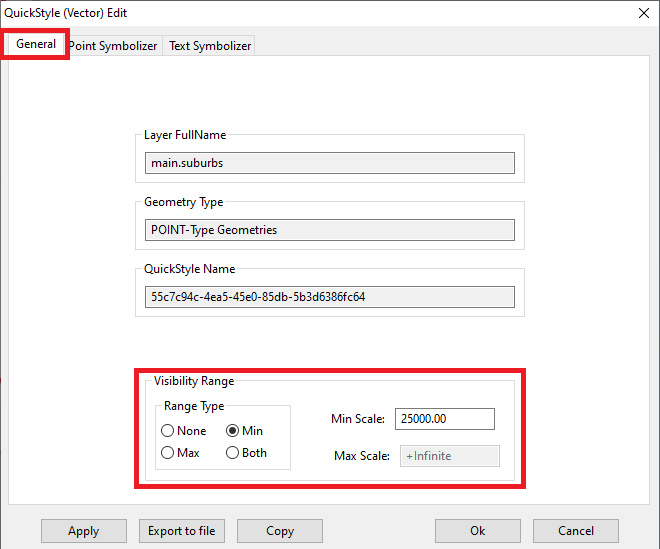
We'll start by examining the General tab of the QuickStyle dialog.
Note: we've defined a conditional Visibility Range
Features belonging to Railway Stations will be drawn on the Map only for scales lesser than 1:25,000
|
| 
|
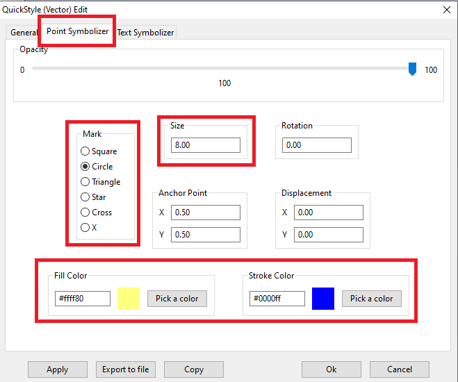
We'll now continue by examining the Point Symbolizer tab of the QuickStyle dialog.
Basic parameters:
- the POINT Geometry will be represented on the Map by using a well-known Mark, that is one of the following simple conventional shapes:
- Square, Circle, Triangle, Star, Cross or X
- This Mark will have the selected size (in pixels).
- The Mark effectively is a small polygon: so it requires a Stroke color (for drawing the border) and a Fill color (for filling the interior).
|
Strange Quirks:
- The Mark can be more or less opaque:
- opacity is complementary to transparency
- Beware: a value of opacity=0 corresponds to full transparency, and consequently the Mark will be completely invisible !
- the Mark can be eventually affected by a rotation; this is sometimes usefull in order to transform a Square into a Diamond, or for changing the orientation of Stars and Triangles.
- The Mark has an Anchor Point, that usually coincides with the centroid of the symbol.
- The Mark could be eventually be displaced by some factor on one or both of the axes.
|
| 
|
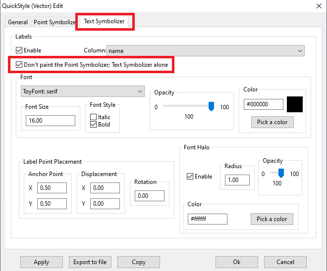
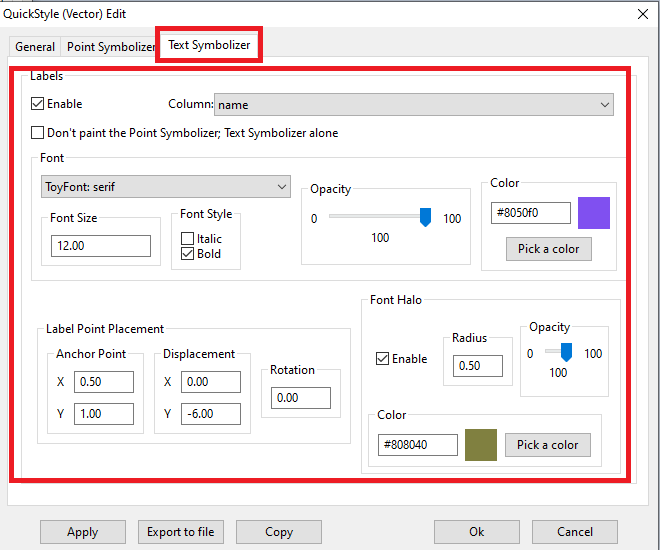
We'll finally examine the Text Symbolizer tab of the QuickStyle dialog.
Basic parameters:
- Printing or not a textual label is optional: you need to check Enable for activating it.
- the name of the column containing the label value must be specified.
- a Font must be defined by specifying:
- a Font name
- a Font size (in pixels)
- an eventual Font style choosing between Normal, Italic, Bold or Bold+Italic
- a Font color
- an optional halo can be eventually defined; this is a thin ring around each letter of the label useful for evidencing the text over the background.
- the halo has a configurable thickness (radius)
- and a color (possibly one strongly contrasting with the Font color).
|
Strange Quirks:
- both the Font and the Halo can eventually have their own opacity (they are mutually independent)
- as we have already seen for PointSymbolizers also TextSymbolizers may have:
- a rotation (applying to label text as a whole).
- an Anchor Point and a Displacement
|
Note:
- In this specific case we've set both Anchor Point and Displacemente in such a way that the text of the label will never overlap the Mark itself.
It will be printed horizontally centered but vertically displaced below the Mark representing the POINT
|
| 
|
This is the XML SLD/SE document representing the Railway Stations Style.
<?xml version="1.0" encoding="UTF-8"?>
<FeatureTypeStyle version="1.1.0"
  xsi:schemaLocation="http://www.opengis.net/se http://schemas.opengis.net/se/1.1.0/FeatureStyle.xsd"
  xmlns="http://www.opengis.net/se"
  xmlns:ogc="http://www.opengis.net/ogc"
  xmlns:xlink="http://www.w3.org/1999/xlink" xmlns:xsi="http://www.w3.org/2001/XMLSchema-instance">
	<Name>9b28a4c4-b57c-42fc-829d-797595a9e843</Name>
	<Description>
		<Title>Quick Style</Title>
		<Abstract>Created by SpatialiteGUI</Abstract>
	</Description>
	<Rule>
		<MaxScaleDenominator>25000.00</MaxScaleDenominator>
		<PointSymbolizer>
			<Graphic>
				<Mark>
					<WellKnownName>circle</WellKnownName>
					<Fill>
						<SvgParameter name="fill">#ffff80</SvgParameter>
					</Fill>
					<Stroke>
						<SvgParameter name="stroke">#0000ff</SvgParameter>
						<SvgParameter name="stroke-width">1.00</SvgParameter>
						<SvgParameter name="stroke-linejoin">round</SvgParameter>
						<SvgParameter name="stroke-linecap">round</SvgParameter>
					</Stroke>
				</Mark>
				<Size>8.00</Size>
			</Graphic>
		</PointSymbolizer>
		<TextSymbolizer>
			<Label>@name@</Label>
			<Font>
				<SvgParameter name="font-family">serif</SvgParameter>
				<SvgParameter name="font-style">normal</SvgParameter>
				<SvgParameter name="font-weight">bold</SvgParameter>
				<SvgParameter name="font-size">12.00</SvgParameter>
			</Font>
			<LabelPlacement>
				<PointPlacement>
					<AnchorPoint>
						<AnchorPointX>0.5000</AnchorPointX>
						<AnchorPointY>1.0000</AnchorPointY>
					</AnchorPoint>
					<Displacement>
						<DisplacementX>0.0000</DisplacementX>
						<DisplacementY>-6.0000</DisplacementY>
					</Displacement>
				</PointPlacement>
			</LabelPlacement>
			<Halo>
				<Radius>0.50</Radius>
				<Fill>
					<SvgParameter name="fill">#808040</SvgParameter>
					<SvgParameter name="fill-opacity">1.00</SvgParameter>
				</Fill>
			</Halo>
			<Fill>
				<SvgParameter name="fill">#8050f0</SvgParameter>
				<SvgParameter name="fill-opacity">1.00</SvgParameter>
			</Fill>
		</TextSymbolizer>
	</Rule>
</FeatureTypeStyle>
|
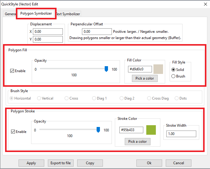
We'll directly start by examining the Polygon Symbolizer tab of the QuickStyle dialog.
Basic parameters:
- The POLYGON Geometry will be represented on the Map by applying two different operations, a fill and a stroke
Note: there is a well definted priority. For each feature fill will always precede stroke
- As the name itself states fill will draw the internal area of the polygon, usually by applying a solid color.
- Stroke will instead draw the borders of the polygon.
Note: a Stroke has a color and a width (expressed in pixels)
- fill and stroke are mutually independent: you are free to use the one or the other or both at the same time.
|
Strange Quirks:
- Both fill and stroke can be more or less opque:
- opacity is complementary to transparency
- As we've already seen for PointSymbolizer, also PolygonSymbolizer can accept a Displacement factor on one or both of the axes.
- A final extravagance: Perpendicul Offset allows to draw on the Map a polygon larger or smaller than the actual Geometry.
In other words a Buffer operation will be applied to the Geometry before actual drawing
- The value of Perpendicular Offset corresponds to the Buffer radius
- Positive values intend a inflated polygon (larger than the original).
- Negative values intend a deflated polygon (smaller than the original).
- Warning: this operator could easily be a real performance killer. Be warned.
- Final curiosity: fill is not necessarily based on some solid color.
You can alternatively apply an half transparent (hollow) brush, an usefull option for saving ink when printing a Map on paper.
- The pre-defined standard brushes supported by QuickStyles are as follows:
- Horizontal lines, Vertical lines, Cross lines, Diagonal lines-1, Diagonal lines-2, Cross diagonal lines and Dots
|
| 
|
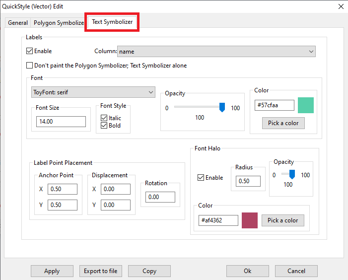
We'll finally examine the Text Symbolizer tab of the QuickStyle dialog.
Basic parameters:
- This Text Symbolizer seems to be strictly similar to the ones we've already seen for Railway Stations and Suburbs.
- And effectively it's the same, because Text Symbolizer for both POINT and POLYGON adopts LabelPlacement / PointPlacement, as you can easily check loocking at the corresponding XML Styles
- In this specific case the implicitly intended POINT corresponds to the centroid of the POLYGON
|
| 
|
This is the XML SLD/SE document representing the Cemeteries Style.
<?xml version="1.0" encoding="UTF-8"?>
<FeatureTypeStyle version="1.1.0"
  xsi:schemaLocation="http://www.opengis.net/se http://schemas.opengis.net/se/1.1.0/FeatureStyle.xsd"
  xmlns="http://www.opengis.net/se" xmlns:ogc="http://www.opengis.net/ogc"
  xmlns:xlink="http://www.w3.org/1999/xlink"
  xmlns:xsi="http://www.w3.org/2001/XMLSchema-instance">
	<Name>dd7422d4-1aaf-43cb-8da9-a51a69040042</Name>
	<Description>
		<Title>Quick Style</Title>
		<Abstract>Created by SpatialiteGUI</Abstract>
	</Description>
	<Rule>
		<PolygonSymbolizer>
			<Fill>
				<SvgParameter name="fill">#d9d0c0</SvgParameter>
				<SvgParameter name="fill-opacity">1.00</SvgParameter>
			</Fill>
			<Stroke>
				<SvgParameter name="stroke">#95b433</SvgParameter>
				<SvgParameter name="stroke-opacity">1.00</SvgParameter>
				<SvgParameter name="stroke-width">1.00</SvgParameter>
				<SvgParameter name="stroke-linejoin">round</SvgParameter>
				<SvgParameter name="stroke-linecap">round</SvgParameter>
			</Stroke>
		</PolygonSymbolizer>
		<TextSymbolizer>
			<Label>@name@</Label>
			<Font>
				<SvgParameter name="font-family">serif</SvgParameter>
				<SvgParameter name="font-style">italic</SvgParameter>
				<SvgParameter name="font-weight">bold</SvgParameter>
				<SvgParameter name="font-size">14.00</SvgParameter>
			</Font>
			<LabelPlacement>
				<PointPlacement>
				</PointPlacement>
			</LabelPlacement>
			<Halo>
				<Radius>0.50</Radius>
				<Fill>
					<SvgParameter name="fill">#af4362</SvgParameter>
					<SvgParameter name="fill-opacity">1.00</SvgParameter>
				</Fill>
			</Halo>
			<Fill>
				<SvgParameter name="fill">#57cfaa</SvgParameter>
				<SvgParameter name="fill-opacity">1.00</SvgParameter>
			</Fill>
		</TextSymbolizer>
	</Rule>
</FeatureTypeStyle>
|
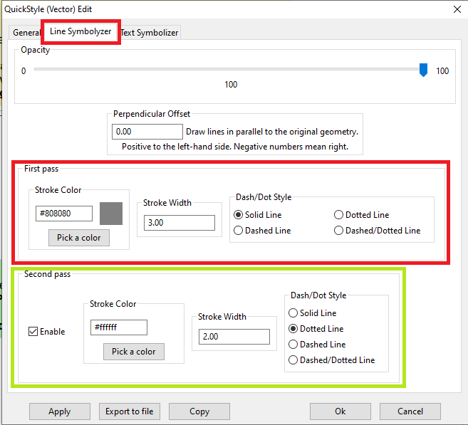
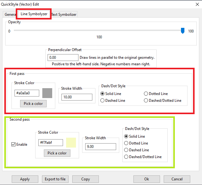
We'll directly start by examining the Line Symbolizer tab of the QuickStyle dialog.
Basic parameters:
- The LINESTRING Geometry will be represented on the Map by applying a stroke operation
As we've already seen in previous examples, defining a stroke implies:
- defining a Stroke color
- defining a Stroke width
- defining a Stroke style choosing between Solid line, Dotted Line, Dashed Line or Dashed/Dotted Line
- In order to get a better loocking style we can eventually activate a second pass
- This is yet another stroke that will over-impress the first one.
- As you can easily notice, we've first defined a larger gray stroke.
- Then we've definer a slightly narrower yellow stroke.
- The overall effect will be a nicely looking yellow line with a thin gray border on both sides.
|
Strange Quirks:
- Both first and second pass strokes can be more or less opque:
- opacity is complementary to transparency
- A final extravagance: Perpendicul Offset allows to draw on the Map a parallel line instead of the originela Geometry.
In other words a SingleSidedBuffer operation will be applied to the Geometry before actual drawing
- The value of Perpendicular Offset corresponds to the Buffer radius
- Positive values intend the left-hand side.
- Negative values intend the right-hand side.
- Warning: this operator could easily be a real performance killer. Be warned.
|
| 
|
We'll finally examine the Text Symbolizer tab of the QuickStyle dialog.
Basic parameters:
- as anticipated a Text Symbolizer supporting LINESTRING requires LabelPlacement / LinePlacement, that strongly differs from what we've already seen in previous examples about PointPlacement.
The default position for a LinePlacement is based on the midpoint of the line, that is the Point dividing the Line in two halves of equal length.
- the most useful and frequently used option is Aligned, intending that all letters of the Label should be nicely arranged along the line so to precisely match the LINESTRING in all its famcy changes of direction and orientation.
|
Strange Quirks:
- the Generalize option intends that the Label shouldn't be directly placed along the original Line but along a derived simplified line.
- the Repeated option requires to print more copies of the Label along the Line distributed at regular intervals:
- Initial Gap represents the distance (in pixels) between the start Point of the Line and the first copy of the Label
- Gap represents the distance between subsequent copies of the Label
- the Perpendicular Offset option as the same meaning we've already seen about LineSymbolizer, this time applied to the Label and not to the Geometry itself.
|
| 
|
This is the XML SLD/SE document representing the Cemeteries Style.
<?xml version="1.0" encoding="UTF-8"?>
<FeatureTypeStyle version="1.1.0"
  xsi:schemaLocation="http://www.opengis.net/se http://schemas.opengis.net/se/1.1.0/FeatureStyle.xsd"
  xmlns="http://www.opengis.net/se"
  xmlns:ogc="http://www.opengis.net/ogc"
  xmlns:xlink="http://www.w3.org/1999/xlink"
  xmlns:xsi="http://www.w3.org/2001/XMLSchema-instance">
	<Name>54a658db-97d0-4fbd-80a8-cd309197820f</Name>
	<Description>
		<Title>Quick Style</Title>
		<Abstract>Created by SpatialiteGUI</Abstract>
	</Description>
	<Rule>
		<MaxScaleDenominator>50000.00</MaxScaleDenominator>
		<LineSymbolizer>
			<Stroke>
				<SvgParameter name="stroke">#a0a0a0</SvgParameter>
				<SvgParameter name="stroke-opacity">1.00</SvgParameter>
				<SvgParameter name="stroke-width">10.00</SvgParameter>
				<SvgParameter name="stroke-linejoin">round</SvgParameter>
				<SvgParameter name="stroke-linecap">butt</SvgParameter>
			</Stroke>
		</LineSymbolizer>
		<LineSymbolizer>
			<Stroke>
				<SvgParameter name="stroke">#f7fabf</SvgParameter>
				<SvgParameter name="stroke-opacity">1.00</SvgParameter>
				<SvgParameter name="stroke-width">9.00</SvgParameter>
				<SvgParameter name="stroke-linejoin">round</SvgParameter>
				<SvgParameter name="stroke-linecap">round</SvgParameter>
			</Stroke>
		</LineSymbolizer>
		<TextSymbolizer>
			<Label>@name@</Label>
			<Font>
				<SvgParameter name="font-family">serif</SvgParameter>
				<SvgParameter name="font-style">normal</SvgParameter>
				<SvgParameter name="font-weight">bold</SvgParameter>
				<SvgParameter name="font-size">10.00</SvgParameter>
			</Font>
			<LabelPlacement>
				<LinePlacement>
					<IsAligned>true</IsAligned>
				</LinePlacement>
			</LabelPlacement>
			<Halo>
				<Radius>0.50</Radius>
				<Fill>
					<SvgParameter name="fill">#ffffff</SvgParameter>
					<SvgParameter name="fill-opacity">1.00</SvgParameter>
				</Fill>
			</Halo>
			<Fill>
				<SvgParameter name="fill">#808080</SvgParameter>
				<SvgParameter name="fill-opacity">1.00</SvgParameter>
			</Fill>
		</TextSymbolizer>
	</Rule>
</FeatureTypeStyle>
|