step#1 - downloading the DXF input files
Now you have to create a new (possibly empty) folder, then saving into it the following DXF files you'll download:step#2 - inserting a custom Reference System
The Spatial Reference System adopted by these Parcel Data seems to be NAD 1983 StatePlane Kansas South FIPS 1502 Feet; such SRS isn't currently supported between the standard ones, so you are now required to manually insert this custom definition: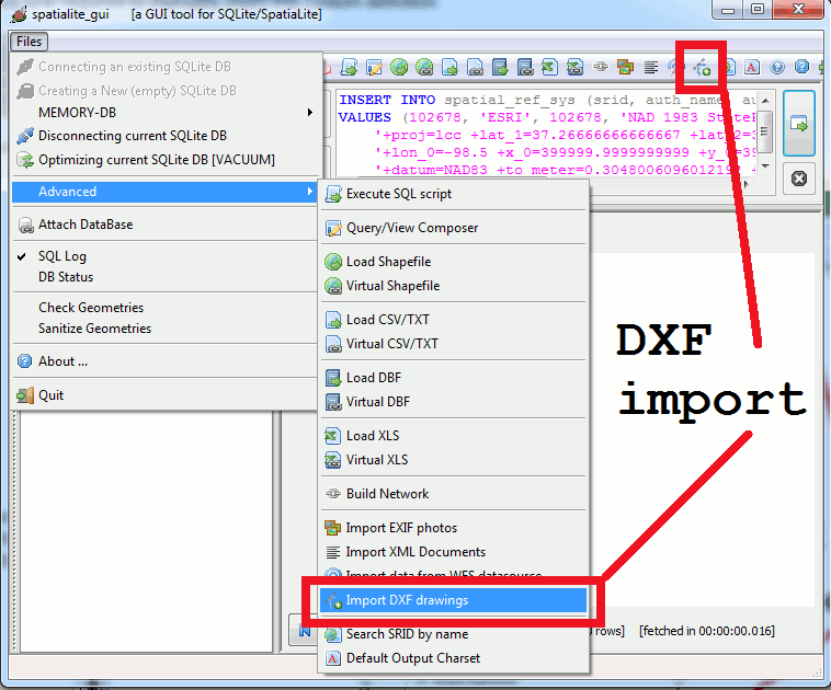
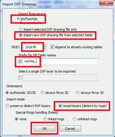
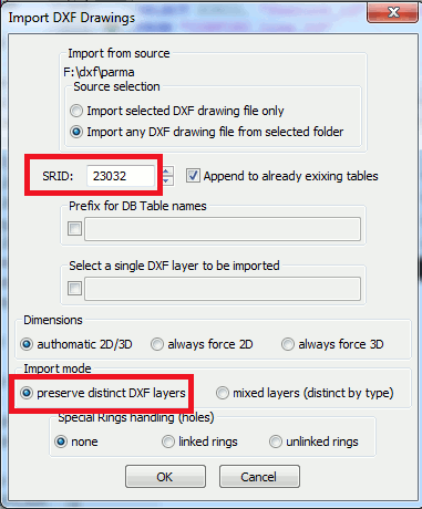
- Please note: you can import more DXF files (actually, a whole folder) in a single step.
- DXFs have no idea at all about SRID: you are always required to explicitly set the appropriate SRID value.
- you can optionally set a prefix for all table-names to be created into the DB; sometimes it's an useful option.
- all DXF theoretically contain 3D data; anyway it's a very common case that the Z coordinate is constantly set as ZERO, so it will automatically be assumed that 2D is the more precise GeoSpatial equivalent.
- any DXF is internally structured by distinct layers: anyway it's often useful reaggregating all layers sharing the same GeometryType and Dimension in the same DB table.
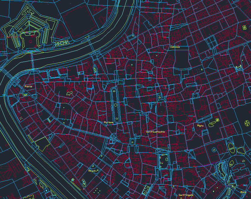
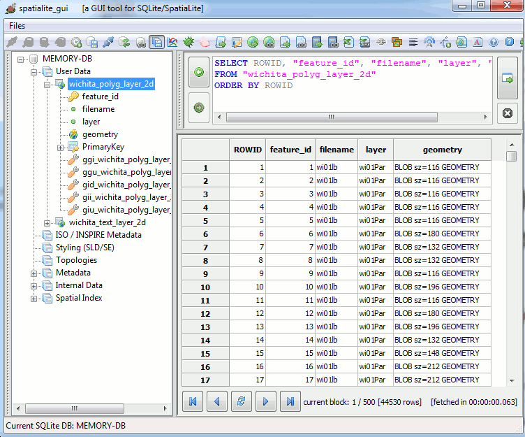
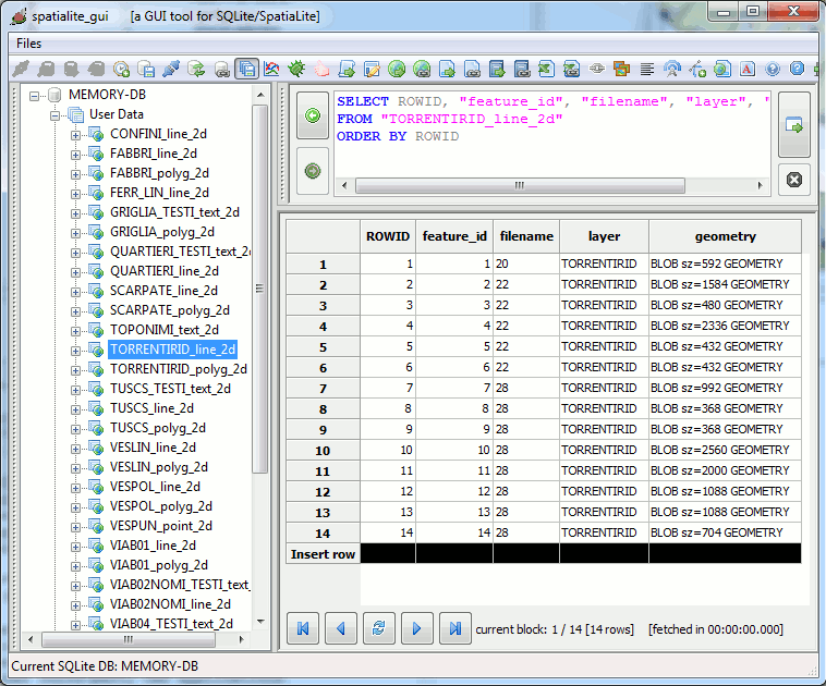
Please note: there are absolutely no lines within Wichita's Parcel Data; this is very uncommon and rather exceptional.
A single DB table will now contain any imported geometry of the polygon type.
Anyway the DXF import tool has carefully preserved a full track of both the origin file and the corresponding DXF layer.
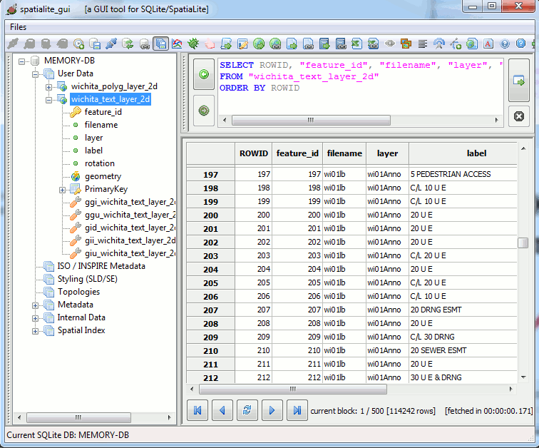
It basically corresponds to a point geometry associated with a text label and a rotation angle.
Downloading the DXF input files
Yet again, you have to create a new (possibly empty) folder, then saving into it the following DXF files you'll download:- In the Parma case the appropriate SRID value is 23032, corresponding to ED50 / UTM zone 32N.
- Now we'll not use any prefix for DB table names.
- And we'll create many distinct DB tables, one for each single DXF layer
Please note: one of most relevant differences between GIS and CAD layers is in that the same CAD layer can easily contain many different kind of Geometries.
This is absolutely not allowed under the more strict GIS/GeoSpatial requirements, where each single layer absolutely has to contain Geometries of the same identical type and dimension.
So a rather impressive proliferation of many different DB tables is what you can reasonably expect while importing DXF data fully respecting the original layers' layout.
Special Rings Handling (holes)
A striking difference between CAD and GIS Geometries is the one related to Polygon's interior rings (aka holes).- The standard GIS/GeoSpatial model dictates that:
- there is always a clear and net distinction differentiating closed linestrings and polygon rings.
- every Polygon must have an exterior ring and could eventually have as many interior rings as required.
- The standard CAD model strongly differs from this:
- a single unqualified Polyline class groups altogether both open Linestrings, closed Linestrings and Polygon rings.
- a special boolean flag is supposed to be activated in order to declare an explicit closure; when this special flag is set we can safely assume that the Polyline effectively corresponds to a Polygon exterior ring.
- there is no (simple) way allowing to define complex Polygons presenting interior rings (aka holes).
Accordingly to all this, many users / organizations have invented during the past years some useful conventional trick allowing to translate GIS Polygons into CAD Polylines (and the opposite) still continuing to fully preserve all holes without any information loss. It looks like the two following criteria are rather popular:
- the unlinked rings conventional representation.
- the linked rings conventional representation.
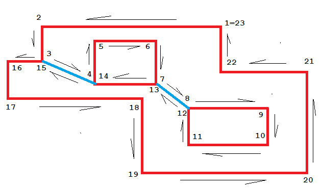
Unlinked Rings
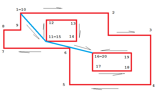
- All Rings belonging to the same Polygon will be simply exported into a single Polyline, just one after the other.
- Some phantom segment will appear joining two consecutive Rings.
- While parsing back the CAD Polyline, each time that a Vertex will be encountered for the second time a Ring should be considered to be completed.
- And the immediately following Segment should be discarded, because it simply corresponds to a phantom segment.
- Finally, all parsed Rings will be re-assembled into a single Polygon.
Linked Rings
- Using this more complex schema, each phantom segment requires to be traversed twice, in opposite directions.
- All segments will then require to be rearranged so to define a path respecting the above constraint.
- While parsing back the CAD Polyline, all segments traversed twice in opposite directions will be discarded.
- Finally, all remaining Segments will be re-assembled into a single Polygon.